Thursday, 14 November 2019

Engine Balance

When talking in terms of engine balance, there are two main states, primary and secondary balance. In it's simplest form, primary balance refers to counter-acting the inertia forces created by the sudden change of direction when a piston passes both TDC and BDC as the piston momentarily attempts to carry on in the previous direction. The amount of force exerted on the piston increases with engine speed.

On an in-line four-cylinder engine, pistons work in sets and the downward (negative) inertia of one set, counter balances and therefore cancels out the upward (positive) inertia of the other. Counterweights are added to reduce twisting action imposed onto the crankshaft by opposing forces and to reduce stress on it's centre main bearing although most engines nowadays use five instead of three crankshaft main bearings in order to provide a stiffer construction.

Single-cylinder engines obviously are unable to use this method as there is only one piston moving up and down and therefore the force, for this reason a counterweight is used on the crankshaft that rotates in the opposite direction of the piston however, the crank and piston assembly will not be balanced horizontally as both the crankpin and connecting rod are travelling in the same plane.

In-line three cylinder engines have the large force of the piston at TDC or BDC cancelled out by the smaller forces of the other two pistons. This also applies to both in-line and vee six cylinder engines.

Secondary balance refers to forces that occur twice during the same revolution as the primary force, which only occurs once per revolution. The distance travelled by the crank and piston assembly during the same amount of time is greater from the top of the rotation (TDC to 90° and 270° to TDC) than it is between  the bottom of the rotation (90° to 180° and 180° to 270°) meaning that the piston is moving faster during the top parts of the rotation. This is what creates secondary imbalance as there is a stronger upward force at TDC and a weaker downward force at BDC. These forces can, depending on engine layout, be cancelled out by adding extra piston or counterweights. Some engines employ a harmonic balancer for this purpose although soft rubber engine mountings are usually used due to cost.

Image result for engine balance diagram
Diagram displaying engine balance

First used in 1911 by Frederick Lanchester to balance out secondary imbalance on in-line four cylinder engines, Mitsubishi also produced a secondary harmonic balancer in 1975 not dissimilar to that of Lanchester, which is now being made and sold under licence to a variety of vehicle manufacturers and engine builders including Saab and Porsche. V4 engines generally tend to incorporate a harmonic balancer in order to keep vibration at an acceptable level. 

The harmonic balancer itself consists of two counter-weighted shafts both taking drive from and timed to the crankshaft. These shafts turn clockwise and anti-clockwise respectively to one another and exert a downward force at TDC. The opposing force of the balancer must be exerted only when needed i.e, when at TDC the shafts must be pointing downwards and at times of low force they must provide a neutral effect as the engine is already in a satisfactory state of balance. 


Image result for secondary harmonic balancer diagram
Operating principles of a secondary harmonic balancer

Aside from primary and secondary balance, all rotating components/masses must also be balanced in order to minimise any untoward vibration such as the complete crankshaft,flywheel and clutch assembly which although ideally dynamically balanced as one assembly, are usually balanced individually due to reasons of cost and locating devices used to ensure the flywheel and clutch run in-line with the crankshaft axis. Removal of metal from the opposing side of a component or/and drilling holes to reduce weight at the heavy point are common methods of correcting imbalance. Pistons and connecting rods can be balanced by ensuring all of their individual weights are equal.

Power strokes of multi-cylinder engines must be regular in order to reduce vibration and the more power strokes in any given 720°  four-stroke cycle, the smoother the engine, torque output and delivery of power from the engine to the road wheels.

Tuesday, 16 May 2017

Sources of power for motor vehicles

Although the internal-combustion engine is by far the best and most efficient way of powering vehicles, both steam engines and electric motors have been used although the steam engine is an external-combustion engine and therefore requires a huge boiler in order to produce steam along with the actual engine. Also, the steam engine is rather bulky and comparatively inefficient due to considerable heat losses from both the engine and boiler, not also to mention that this type of engine continues to consume fuel quite for quite some time after it has been stopped in order to maintain steam pressure, whereas, the internal-combustion engine only uses fuel when running.

Electric motors are increasingly being used to insist the internal-combustion engine such as in hybrid applications although we are also seeing the increase in cars that are ran solely by electricity. However, this has actually been around for quite some time although only in common use for the last 15 years or so as technology has improved and associated components have became considerably lighter and less bulky.

Other drawbacks of electric cars are that they have a limited operating range and therefore require fairly regular recharging, hence the continual increase in "plug-in points" for these vehicles and also the fact that they are limited on speed

A drawback of the internal-combustion engine is that it can take considerable time for it to run at its peak temperature and hence performance whereas the external-combustion engine is still emitting a small amount of steam in order to relieve pressure in the boiler and by opening of a small valve, it will be able to work straight away as like an electric motor can simply just be switched on and used.


Motor Car Evolution


Right back in times immemorable, humans had no alternative other than to carry heavy loads themselves which was not particularly pleasant on the body and both speeds and load handling abilities were severely limited. The only alternative to this was the use of domestic animals such as Horses and Donkeys, which were more often able to carry more heavy loads at a faster pace than humans were able to achieve, with people travelling in comparative comfort.

Theories have existed that sledges and even rounded tree stumps had been used as a basis to transport loads before the invention of the wheel for example; how were the ancient rocks of Stonehenge not only erected on site but how did they get there? Studies have been carried out and the rocks are believed to be native to an area of Wales and some believe they may have been placed on top of cylindrical shaped tree stumps horizontally and pushed!

Fast forward several years and we had wheeled chariots and carts which were obviously able to carry considerably more weight than their predecessors with a drawback being that the wheel needed - and still does - a relatively smooth surface on which to run without getting into ruts and abnormalities in the surface etc. Therefore, as the vehicle has evolved, so have roads.

Initially, steam engines were used to power wheeled vehicles although only a small handful were successful due to weight, low speeds and legislation, however, one successful application was in traction engines which although very slow, noisy and polluting, were able to carry more substantial loads than any road vehicle before it. One of the greatest engineers and evolutionaries of these type of engined vehicles was Cornishman Richard Trevithick 1771-1833, an inventor and mining engineer of whom produced many "steam carriages" several of which were used to assist the mining industry and process in Cornwall amongst other things.


Image result for richard trevithick
Richard Trevithick

Sunday, 23 April 2017

Cylinder Layout & Firing Order

Over the years, there have been several engine designs including different layouts for the cylinders with the most common being of the in-line variety. However the cylinders may also be opposed either in a Vee, W or horizontally.

The pistons of any engine must have their power strokes in succession, this is referred to as the firing order of the engine, which is determined by two main factors including the crankshaft design, which will determine all the possible firing orders and the webs, which are designed in such a way as to provide the best possible balance and to ensure that regular firing strokes occur. The cams on the camshaft must also be arranged in such a way as to adhere to one of the possible firing orders.

Power strokes in an in-line four cylinder engine occur at 180° intervals and the pistons move in pairs with one and four forming one pair and two and three forming the other. For instance,in a four cylinder in-line engine with a firing order of 1,3,4,2, if piston two is on induction stroke, piston three will be on its power stroke, and pistons one and four on their compression and exhaust strokes respectively.

The power strokes of an engine must be spaced at uniform intervals with every interval being equal to the number of degrees per engine cycle divided by the number of cylinders. For example, the calculation used to determine the number of degrees between strokes on a four cylinder is as follows;

Number of degrees per engine cycle/number of cylinders
(720°/4) = 180°

On an in-line four-cylinder engine, the two possible firing orders are 1,3,4,2 or 1,2,4,3 as found on some engines. If the firing order were to be 1,2,3,4, the crankshaft and engine mountings would be subject to such high levels of vibration and stress that it would be unbearable to the vehicle occupants and the engine components would very soon wear out under such high levels of fatigue.
The firing order can be found in workshop manuals and various manufacturers literature. It may also be marked in a prominent place on the engine itself. This my also be defined by turning the engine in its normal direction of rotation with the rocker/camshaft cover removed and watching the order of which either the inlet or exhaust valves operate or to note the order by which the cylinders create pressure on compression stroke by means of turning the engine with the spark plug holes either covered by thumb or finger or appropriately plugged. This test can also be performed using a cylinder pressure gauge.

The cylinders of a straight engine are formed in a straight line parallel to one another and may be opposed either vertically  or slanted at an angle such as those found in early Saabs, the Hillman Imp and certain Triumph models. Owing to the reasonably spaced power strokes, this type of engine is relatively smooth in operation and any vibration or harshness is largely unnoticed by the vehicle occupants as rubber engine mountings damp out much of this.

In the most common cylinder layout found in the motor vehicle, the aforementioned in-line, the number of cylinders varies from design to design with four being the most popular however many manufacturers are now moving to three-cylinder engines for reasons of reduced emissions and compaction. In the past however, some designs have used as little as two cylinders and as many as eight as the straight eight engine was much cheaper to manufacture than its V8 counterpart. But this design was superseded many years ago. Other numbers in common use are five and six cylinders but again, the straight six engine has largely given way to the V6 although it is still in use by certain car makers.


Monday, 6 March 2017

How the number of cylinders effects engine behaviour


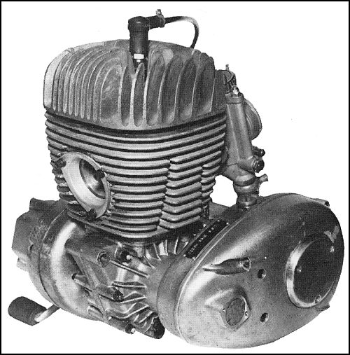
In its simplest form, an engine has a single cylinder, although this is not suitable for motor car applications as the torque would be very uneven due to the fact that there is just one power stroke for every two crankshaft revolutions and the vibration that would occur as a result. This design is however commonly used in motorcycles and some microcar applications. One example of which is the Villiers engine as shown below;

Villiers Starmaker

The minimum amount of cylinders required to provide acceptable levels of vibration and harshness in motor cars is two, giving one power stroke per crankshaft revolution although, compared to engines with larger numbers of cylinders, the vibration at low speeds is still very much noticeable. In the case of a single-cylinder engine, even a large flywheel designed to store this energy would be inefficient in giving smoother running at lower speeds. 

Motor vehicles today use typically anything from 2 to 12 cylinders, all of which can be arranged in a number of ways. The average torque value of a four-cylinder engine will be greater than that of a single-cylinder engine of the same displacement however, the maximum torque value generated by each individual cylinder would be significantly lower than that of a single cylinder engine of the same displacement.

Torque delivery is much smoother with multi-cylinder engines owing to that fact that the more cylinders an engine has, the more power strokes per crankshaft revolution. Multi-cylinder engines also have the added advantages of being safer at higher speeds, a greater ability to develop more power and have longer lives due to less uneven torque and vibration. Although multi-cylinder engines are essential for smooth running in motor car applications, there is the obvious drawback of the fact that they are more complicated in their design due to the increased number of parts and overall cost of manufacture.

Traditionally, more cylinders meant more power however nowadays, manufacturers are continually moving towards the trend of smaller engines due to emissions laws. Thanks to modern technology, smaller engines can now produce much higher power outputs and it is not unheard of for these aforementioned engines to produce more power than older engines of more than twice their size or capacity.

In certain cases, high-performance supercars have now taken to using W-engines, incorporating up to 18 cylinders

Image result for w18 engine
A W16 engine of the Bugatti Veyron

Sunday, 8 January 2017

The Two Stroke Cycle


Dugald Clerk v. 1904
Dugald Clark, the inventor of the two-stroke engine

Developed in the late 19th century by Scottish engineer Dugald Clark, the two-stroke engine has been used in a handful of production cars and several motorcycles and can be found in both spark-ignition and compression-ignition forms, although the latter is not very common. An advantage of this engine was that there were less strokes meaning that the complete cycles was complete within two revolutions of the piston and only one of those strokes was the engine not producing any power as opposed to three in a four-stroke engine. These engines run on a mixture of fuel and lubricating oil with typical ratios of fuel-oil being around 32-40:1. It would be Joseph Day's modification of this engine that would first come into use some ten years later and the fundamentals of it's workings in both petrol and diesel forms are described as follows:
In the case of a two-stroke petrol engine, beginning with the piston approximately half way up the cylinder, and all the relative ports covered, the rising piston compresses the mixture above and pressure below the piston is reduced. as the piston passes TDC, a fresh air:fuel mixture is forced into the crankcase by atmospheric pressure and the piston is now at the top of its stoke. The mixture above the piston is now ignited and the high pressure of these burnt gases forces the piston downwards, as is the case with the four-stroke engine. As the piston is nearing bottom dead centre, the fresh mixture in the crankcase is now compressed and the burnt exhaust gases are forced out of the cylinder under their own pressure. as the piston passes BDC, the transfer port is now uncovered and the compressed mixture below can now flow into the cylinder above the piston and is deflected upwards by a specially shaped deflector formed on top of the piston, preventing it from escaping across the cylinder and out of the exhaust port however, in modern two-stroke engines, the dispenser is no longer used as the transfer ports are shaped and aimed towards the top end of the cylinder and away from the exhaust port.
Although this engine has advantages of being simple in design, relatively smooth in operation and has just one idle stroke to one working stroke, it is still much less effective in its operations as some of the fresh mixture can easily be mixed with the exhaust gases and escape through the exhaust port and incomplete scavenging of burnt gases from the cylinder can occur.
Less common is the two-stroke diesel engine, which originally was used for low-speed industrial and marine applications and is now fitted to a handful of commercial vehicles. This engine has the advantages of being smooth, small and simple in its construction. Also, the loss of fuel to the exhaust when both ports are open is not an issue to this design as the cylinder contains only air.
The sequence of operations are as follows;
As air enters the inlet port, exhaust gases exit via the exhaust port and both ports are then closed by the ascending piston, providing the compression stroke. The air has now been compressed to a ratio of 12-16:1 and at this point the fuel is injected into the cylinder and ignited by the heat of the compressed air, producing the power stroke.
Most of these engines will incorporate a a blower to pressure-charge the cylinder with air to ensure the supply is adequate however, the engine can be operated by making use of pressure waves or pulses in the exhaust system to induce new air into the cylinder.
In the case of uniflow-type two stroke engines, an exhaust valve is incorporated and roots-type blower used to compress air into the cylinder improving engine output and breathing as it enables more air and fuel to be drawn in and exhaust gases to be evacuated more efficiently, potentially giving the same power of a four-stroke engine of the same displacement. By the time the air ports are uncovered, the exhaust valve has already opened, allowing the remaining gas pressure to start pumping out the exhaust gas, followed by an air charge approximately 30% greater in volume than the cylinder capacity, cooling and scavenging the cylinder more effectively.
Image result for uniflow two-stroke engineImage result for uniflow two-stroke engine

Sunday, 11 December 2016

The Four Stroke Cycle

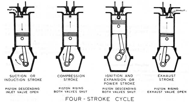
Image result for four stroke cycle diagram

1. As the inlet valve opens, the piston moves down the cylinder and a mixture of air and fuel, or just air in the case of a diesel engine, is drawn into the cylinder via the inlet port until the piston reaches the bottom of its travel within the cylinder (bottom dead centre) or BDC. This is referred to as the induction stoke.


2. With the inlet valve now closed, the piston will now begin to move back up its cylinder, compressing the charge in the process. as the piston nears the top of its travel, the mixture is now in a highly compressed state and at an extremely high temperature. This is referred to as the compression stroke


3. With the piston now at, or a few degrees before or after its highest point (top dead centre) or TDC, the mixture is now ignited by a spark, in the case of a petrol engine or by heat of the compressed air in a diesel (diesel engines have much higher compression ratios than their petrol counterparts due to diesel fuel being less flammable and in the absence of a spark) causing an explosion, which creates the engines power, hence this is referred to as the power stroke.

4. As the piston reaches its lowest point once again and starts to work its way back up, the exhaust valve is now open and the burnt gases which are a result of combustion will begin to exit the cylinder and follow on to the exhaust system. When the piston reaches the top of its travel, all of the gases will have been expelled from the cylinder and the exhaust valve is now closed. This is referred to as the exhaust stroke.


Although this cycle of operations generally refer to petrol (spark-ignition or S.I engines), the four-stroke cycle is very similar for diesel or compression-ignition (C.I) engines although there is a very brief break between the time from which the fuel is injected into the cylinder and that of when it is ignited by the heat of the corresponding compressed air. This is known as the "Delay Period"


It must be noted that only on the power stroke is any real work being done as there is no power being produced on any of the other three strokes. For this reason, the flywheel must assist in keeping the
engine turning over and also for smooth running in between strokes.