Sunday 11 December 2016

The Four Stroke Cycle

Image result for four stroke cycle diagram

1. As the inlet valve opens, the piston moves down the cylinder and a mixture of air and fuel, or just air in the case of a diesel engine, is drawn into the cylinder via the inlet port until the piston reaches the bottom of its travel within the cylinder (bottom dead centre) or BDC. This is referred to as the induction stoke.


2. With the inlet valve now closed, the piston will now begin to move back up its cylinder, compressing the charge in the process. as the piston nears the top of its travel, the mixture is now in a highly compressed state and at an extremely high temperature. This is referred to as the compression stroke


3. With the piston now at, or a few degrees before or after its highest point (top dead centre) or TDC, the mixture is now ignited by a spark, in the case of a petrol engine or by heat of the compressed air in a diesel (diesel engines have much higher compression ratios than their petrol counterparts due to diesel fuel being less flammable and in the absence of a spark) causing an explosion, which creates the engines power, hence this is referred to as the power stroke.

4. As the piston reaches its lowest point once again and starts to work its way back up, the exhaust valve is now open and the burnt gases which are a result of combustion will begin to exit the cylinder and follow on to the exhaust system. When the piston reaches the top of its travel, all of the gases will have been expelled from the cylinder and the exhaust valve is now closed. This is referred to as the exhaust stroke.


Although this cycle of operations generally refer to petrol (spark-ignition or S.I engines), the four-stroke cycle is very similar for diesel or compression-ignition (C.I) engines although there is a very brief break between the time from which the fuel is injected into the cylinder and that of when it is ignited by the heat of the corresponding compressed air. This is known as the "Delay Period"


It must be noted that only on the power stroke is any real work being done as there is no power being produced on any of the other three strokes. For this reason, the flywheel must assist in keeping the
engine turning over and also for smooth running in between strokes.

Monday 17 October 2016

Primary components of the engine

Image result for engine main components
Diagram of an overhead camshaft spark ignition (petrol) engine showing main components


1. The cylinder block - This contains the cylinders, pistons, connecting rods and crankshaft, oilways of the lubrication system, coolant passages of water-cooled engines and in the case of overhead and side-valve engines, the camshaft and pushrods. The cylinder block and crankcase can be separate but are usually cast as one, and usually from either cast iron or aluminium alloy, which is lighter and a better conductor of heat. In water-cooled applications, the water jacket, surrounds the cylinders and are designed to and contains passages through the block which cooling water passes through in order to maintain the engine at optimum temperature and is linked with that of the cylinder head via corresponding passages. Core plugs are provided in the block and are designed to dislodge in the event of the coolant expanding due to freezing, which could crack the cylinder block. The core plugs also seal holes created during the casting of the block and various mountings are provided for components such as water pumps and distributors etc.

2. The cylinder head - This contains the valves, valve ports and the relevant operating gear which includes the camshaft and followers in an overhead camshaft design and the rocker gear for opening the valves on an overhead valve design. Again,  cast iron and aluminium are typical materials used in cylinder head construction with aluminium being most popular for performance and race engines due to its lightweight and ability to conduct heat. However, inserts are required to harden and therefore strengthen valve seats and guides in heads using the latter material and where an alloy head and cast iron block are used, an effective seal between the two can be hard to achieve given that the two metals heat, cool, expand and retract at different rates. The faces of both the cylinder block and head are machined flat in order to mate properly and a gasket is normally used in between the two however some designs rely on perfectly flat faces to provide a reliable fluid tight seal. Any distortion caused by overheating of either head or block faces can lead to gasket failure, resulting in the leakage of oil, gas or/and water and the three mixing together inside the engine, Combustion chambers and exhaust ports are the hottest areas of the cylinder head and therefore must be adequately cooled.

3. The crankshaft - The main shaft of the engine which is carried in bearings in the crankcase and has crankpins offset from the main journals, which carry the connecting rods (often abbreviated to con-rods) and is free to rotate

4. The cylinders - Simply, tubes formed in the cylinder block in which the pistons reciprocate

5. The pistons - Cylindrically shaped and fit tightly into the cylinders, forming an airtight seal

6. The connecting rods - These connect the pistons to the crankshaft and are held in places by "gudgeon pins" formed in the pistons at the "small-end" and Big end bearings in which the crankpins rotate. It is these connecting rods that allow the reciprocating movement of the pistons to be transferred into the rotational movement of the crankshaft that passes on the engine power to the drivetrain in order to propel the car.

7. The camshaft - The camshaft is located in the cylinder head (overhead camshaft) or in the cylinder block (overhead valve) and is responsible for the opening of the valves in turn at the correct time and the durstion of which the valves remain open.


Tuesday 9 August 2016

A brief history of the motor car as we know it

Contrary to popular belief, the motor car was not necessarily invented by anyone, it was merely an evolution of its forefathers the horse and cart, of which the latter which was then successfully propelled by steam alone, and the tricycle. These were then commonly referred to as horseless carriages

In 1860, Belgian inventor Etienne Lenoir built the first practical example of the internal combustion engine.

Etienne Lenoir 1822-1900 and his famous engine

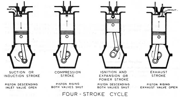
Throughout the next two decades, numerous experiments were carried out to bring the concept of self-propulsion to light. A breakthrough came in 1874 when Austrian inventor Siegfried Markus built a small cart powered by a four-stroke engine which was itself then successfully installed by German engineer Count Nicholas Otto in 1876 hence the name “Otto Cycle” which is still used to describe the working principles of the four-stroke engine today. Before this, vehicles ran on steam.

An early Otto engine

Steam engines would still be widely used on trains in Britain until the mid 1960’s. The main difference of these engines is that steam engines rely on external combustion, simply meaning that the fuel is burnt outside of the cylinders and internal combustion engines burnt their compressed mixture of air and then coal gas inside their cylinders. But once petrol was used instead of coal gas, it could then be made mobile and efficiency improved greatly. The birth of the motor car was soon to follow.


The persons responsible for the motor car today are those who first made it work. Gottlieb Daimler (1834-1900) and Karl Benz (1844-1929) (both of whom are pictured above respectively) the former having worked for Otto and then setting up alone in 1882 where he was joined by fellow Otto graduate Wilhelm Maybach. Together, they came up with the Daimler-Maybach engine which could run at speeds up to 900 rpm, some 700 rpm more than the engines of Otto. Daimler’s engines evolved constantly and swiftly and his single-cylinder engine soon evolved to a twin-cylinder vee engine fuelled by a carburettor of Maybach’s design using a hot-tube ignition system in which fuel was ignited by a small platinum pipe kept red-hot by a burner.

Benz also developed a four-stroke engine which used a singer-cylinder arrangement producing ¾ hp. This engine used the innovation of spark ignition in favour of hot-tube, and in 1885, this engine would be used to power the car he designed and carried his name, which was the first of its type having three wheels, two seats and was capable of 8 mph. This engine featured the mushroom shaped poppet valve and water-cooling, both of which survive today! The water did however not circulate, it was stored in a tank and would burn away therefore topping up was frequent. The drawbacks of this engine in comparison to those of Daimler were that they were heavier and ran at less than half the speed. This car was introduced to the public in 1887 however the year before Daimler had introduced a four-wheeled vehicle with a vertically opposed engine producing 1 ½ hp, and it was this engine that would live on into the following century.

Subsequently, Daimler approached lawyer Edouard Sarazin who was well-known in his day for handling claims from numerous inventors all claiming name to these innovations. Sarazin, who held the French patent on Daimler’s engine, introduced it to Emile Levassor (1843-1897) and Rene Panhard (1841-1908) who agreed to build the engines in France providing they not be assembled using imported parts from Gottlieb Daimler. The first model was built in 1890 using a centrally mounted engine with another front-engined model being introduced the following year so that it would not be subject to road debris being thrown up from the roads of the late 19th century which would have been little more than dirt tracks.

The mechanical layout of this car would then dominate the motor car industry for many years to come. Levassor would then go on to introduce other aspects to the motor vehicle as we know it such as scrapping belt transmission in favour of a clutch and gearbox, the front-engine rear-drive arrangement and the gilled-tube radiator. By the turn of the century the motor car had its own unique identity and was being built all over Europe and the United States of America.

During the early days of motoring, a law was laid down, known as the “red flag law” in which propelled vehicles would be restricted to a speed limit of 4 mph across the country and 2 mph in built up areas with a man who would walk 60 yards in front of the car carrying a red flag. This law was abolished in 1878 however, somebody was still required by law to walk a minimum of 20 yards in front of the car, assisting horse drawn carriages as necessary until 1896.

In celebration of this abolition, an emancipation run from London to Brighton took place, in which red cloth was torn up and speeds of up to 14 mph were reached!. It was this run which would go on to inspire the London to Brighton veteran car run today. Since these early days of the motor vehicle, it has gradually evolved into the motor vehicles of today that many of us have became accustomed to.

1885 Benz patent. One of the first motor cars ever built
Detail showing the unique engine layout of the 1885 Benz